Robot Quick Changer, the industry is also known as End of Arm Tooling, Quick Changer, Robotic Tool Changers, Quick Change Connector, etc., it is applied to the end of the industrial robot a flexible connection tool, is a very important part of the industrial robot application system, its role is to allow a single industrial robot in the application process to automatically switch between the different end of the implementation of the tool to increase the flexibility of the use of industrial robots, with the production line to replace the fast, effectively reduce downtime, one machine multi-purpose and many other advantages, give full play to the performance of the robot, improve the cost-effectiveness of industrial robots. It has the advantages of quick change of production line, effective reduction of downtime, multi-purpose, etc., which gives full play to the performance of the robot and improves the cost-effectiveness of industrial robots. Robot quick changer is widely used in automatic spot welding, arc welding, machine loading and unloading, automatic handling, 3C electronics, new energy batteries, semiconductors, stamping, testing, assembly, grinding, packaging palletizing, and other industries.
Undoubtedly, in the use of industrial robots, ensuring the safety of the automation process is the primary consideration, the robot quick changer because of the need for different end-of-execution tools between the automatic switching, which for the safety of the higher requirements, the robot quick changer is mainly through the two ways to ensure its safety: the first is the quick-changer itself mechanical locking mechanism, the second is through the external control unit, the following two ways to ensure the safety of the quick changer, the second is through the external control unit, the second is to ensure the safety of the robot quick changer. The second is through the external control unit, the following two cases are described.
Robot Quick Changer is divided into the robot side (Robot side), referred to as the R side and the tool side (Tool side), referred to as the T side of the two parts, the robot side is installed in the end of the robot, the tool side and the implementation of the tool (welding gun, robot, fixtures, etc.) installed together, the robot side is mainly composed of the body of the quick changer, the mechanical locking mechanism, the optional module, and the control unit of four parts, the tool side is used in conjunction with the robot side, is relatively simple. The tool side is used with the robot side, relatively simple, with no control unit part, the rest of the parts, and the robot side to maintain consistency. In the industry, the world’s mainstream mechanical locking mechanism has the following types:
The first type: is the steel ball and spring self-resetting locking mechanism, as shown in Figure 1
The whole set of locking mechanisms consists of a large thrust spring, piston, steel ball, and cam composition. Its working principle is the piston and cam connection, in the compressed air and the role of the spring to promote the steel ball to complete the locking; loose when the piston drives the cam back, at this time the steel ball can be retrieved; when the locking mechanism accidentally drop air when the steel ball at the end of the tool under the action of gravity will be moved by the locking platform to the safety platform, at this time in the large thrust spring thrust and the action of the tool under the action of the steel ball on the cam to achieve hold dead, the safety platform and the large The double insurance locking mechanism of safety platform and large thrust spring has high safety when the system accidentally drops gas, the representative enterprises of this kind of mechanism are Switzerland Stäubli, Jfurther and so on.

The second type: steel ball springless locking mechanism
The whole locking mechanism consists of a piston, steel ball, and cam. Its working principle is the piston and cam connection, under the action of compressed air to promote the steel ball to complete the locking; loose when the piston drives the cam back, at this time the steel ball can be retracted; when the locking mechanism accidentally dropped gas when the steel ball at the end of the tool under the action of gravity will be moved by the locking platform to the safety platform, at this time in the tool under the action of gravity to realize the steel ball on the cam of the hold dead. Safe platform set locking mechanism in the accidental fall of air to provide the basic safety and protection, this kind of mechanism on behalf of the type of enterprise has the United States ATI, Germany SCHUNK and so on.
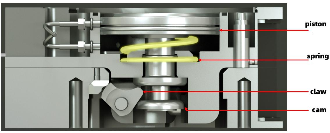
The third type: claw type locking mechanism, as shown in Figure 2
The whole set of locking mechanisms by the piston, claw, and cam composition. Its working principle is: the piston and cam connection, under the action of compressed air to drive the claw to complete the locking; loosening the piston to drive the cam to retrieve the claw; when the locking mechanism accidentally fall out of the cam in the spring force to keep the top out of the action, relying on the spring force to protect the locking mechanism in the accidental fall out of the air with the basic safety and protection of the mechanism on behalf of the enterprises in Japan, such as NITTA.
Above we elaborated from the mechanical locking mechanism point of view of the robot quick changer how to realize the safety, next we look at the external control unit from the robot quick changer part of how to realize the double safety guarantee. From the above analysis of the mechanical mechanism, the quick changer locking mechanism of the power mainly from the internal cylinder, so for safety, is to realize the cylinder releases the control of the air source, to prevent the occurrence of accidental unlocking, at present the industry’s commonly used control methods have the following kinds:
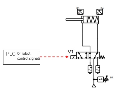
The first: the single-valve direct control mode, as shown in Figure 3
This is a very simple control method, no additional safety measures, by the PLC or robot signal direct control, the advantage is simple control; the disadvantage is that there are no additional safety measures, and any position, any time can be unlocked with external instructions.
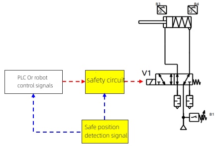
The second: the single-valve safety control mode, as shown in Figure 4
Additional safety measures, PLC or robot signals need to be controlled by the safety circuit, the advantages are simple control, increase additional safety measures, safety circuit can only be unlocked through the designated safety position; the disadvantage is that the safety circuit is single, the safety level is insufficient.
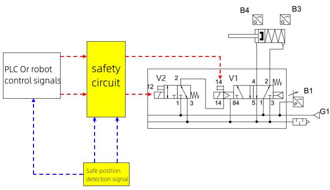
The third: the dual-valve control mode, as shown in Figure 5
The use of 2 solenoid valves to achieve safety control, the safety position detection signal is increased to double detection, the advantage is that there is a safety protection circuit, the use of more reliable safety switches, the use of two solenoid valves, the safety of the air line is more reliable; the disadvantage is that the main air line is still a single valve, not to achieve true redundancy.
The fourth: PLd level double valve control mode, as shown in Figure 6
The use of two more highly reliable safety solenoid valve to achieve safety control, not only the safety position detection signal increased to double detection, and real-time diagnostics on the operating status of the quick-change and solenoid valve operation, when a fault is detected, the quick-change automatic alarm and maintain the safety locking state, the advantage is that the circuit to increase the state of the monitoring and safety protection circuit, the use of more reliable solenoid valves, the use of the main air circuit with two solenoid valves, safety The air circuit really realizes redundancy, the whole can reach PLd; The disadvantage is that the price is higher.
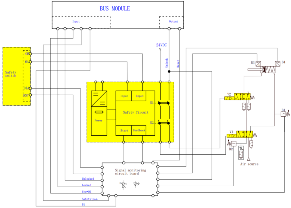
The fifth type: the Jfurther safety control box method, as shown in Figure 7
Jfurther has developed a safety control box specifically for quick changer, with a safety level of PLd, Cat.3. The control box integrates a comprehensive signal diagnostic function, which enables monitoring of the following conditions:
- Monitoring of the locking and unlocking action of the quick-change, i.e., prevention of internal mechanical failures.
- Monitoring of the air supply pressure, i.e. monitoring of the locking air supply at all times during operation.
- Monitoring of the status of the solenoid valves, i.e. to prevent mechanical failures of the valve body.
- Monitoring of the status of the safety switches, i.e. timely feedback of fault signals.
- Internal monitoring of the safety output circuits, i.e. to prevent device failure.
- Locking of safe output circuits, i.e., must be reset in the event of a malfunction.
- Initialization requirements for the safety output circuit, i.e., the device must be powered up to perform the reset operation and complete the internal self-test function.
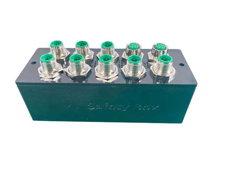
The above introduction of the various external air control methods, safety performance gradually incremental, in the global robot quick changer manufacturers, the safety performance of the current PLd, Cat.3 level of the few companies, Jfurther as a domestic robot quick changer segment of the pioneer, has reached the industry’s mature technology, the previous industrial robots used in the robot quick changer are almost all monopolized by foreign brands, with the rise of the domestic manufacturing industry, the national attention, and support for core components, a number of key components of the robot to achieve complete localization, as part of which contribute to the industrial value of the people belonging to the Jfurther. With the rise of the domestic manufacturing industry, the country’s attention to the core components and support, a number of key components of the robot to achieve complete localization, Jfurther is a part of which contributes to the industrial value of the Jfurther people.
